Michael Wrona's Blog
Engineering, coding, tech, and other cool projects!
Read Serial Data From Spektrum Remote Receiver
About six years ago, I purchased a Spektrum DX6i RC plane transmitter to fly my RC planes with. Unfortunately, life got busier and my interests shifted, which sent my planes and controller to retire in the basement. When the idea to build a quadcopter flight controller began to come to fruition, I knew my DX6i controller would be perfect! “This is a cause worth coming out of retirement for, old one” I said to my controller. His response: not powering on. I guess it’s time for some fresh AA’s.
Introduction
I was initially going to use my Spektrum AR6210 6-channel receiver to provide pilot inputs to my quadcopter. I’d use my microcontroller’s digital pins to read the PWM signals from each channel. Unfortuantely, reading six PWM channels would require six individual servo cables running from the receiver to the microcontroller, which would look messy and add extra weight to the drone. Since this was basically my only option given the materials I had, I was willing to compromise.
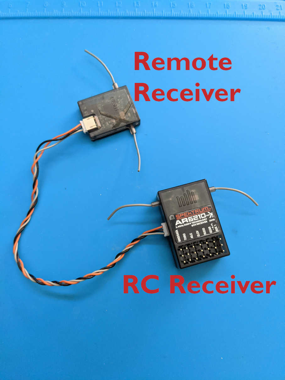
I had always wondered what the little dongle-thingy was attached to my AR6210 receiver. I did some research and discovered this was a Spektrum DSMX Remote Receiver. I did some more digging and found out that the three wires connecting the remote receiver to the AR6210 were power (+3.3V, orange), data (gray), and ground (black) wires. It turns out that the connection between the two was a serial connection that contained channel data! After this amazing discovery, I began reverse engineering the DSMX communication protocol and eventually succeeded: I figured out how to extract the six channel/transmitter stick positions from the DSMX serial byte stream. Now, time to tell you how to do the same!
First, I’ll describe the DSMX communication protocol and serial packet structure. Next, I’ll outline my hardware testing setup and wiring. Finally, I’ll dive deep into the Arduino code I developed to read and process the remote receiver’s serial data stream.
DSMX Communication Protocol
Datasheet Reference: The official data sheet describing the Spektrum Remote Receiver communication protol can be found at this link.
The serial communication protocol used by Spektrum Remote Receivers consists of 16-byte transmission packets. There are four different serial communication protocols used by the receivers, differentiated by the timing between transmissions and channel data ranges.
| Protocol | ID Byte | TX Timing | Ch. Data Range |
|---|---|---|---|
| 11ms/2048 DSM2 | 0x12 | 11ms | 0 … 2048 |
| 22ms/1024 DSM2 | 0x01 | 22ms | 0 … 1024 |
| 11ms/2048 DSMX | 0xB2 | 11ms | 0 … 2048 |
| 22ms/2048 DSMX* | 0xA2 | 22ms | 0 … 2048 |
The timing between each serial data packet transmission is either 11ms or 22ms, and the channel data ranges from zero to either 1024 or 2048. My particular Remote Receiver used the 22ms/2048 DSMX (denoted by *) protocol. I am assuming this is the most common.
Packet Structure
Each 16-byte serial data packet has the following structure:
| Byte Index | 0 | 1 | 2 ... 15 |
|---|---|---|---|
| Field Name | Fades | Proto. ID | ServoData[7] |
| Data Type | uint8_t | uint8_t | uint16_t |
The first byte in the transmission is referred to as ‘fades’ in Spektrum’s datasheet. This is a count of how many data packets were missed by the remote receiver. My receiver never missed any frames during testing (even when I did a range test), so I guess there’s no need to keep track of this value in your code. The second byte is the protocol ID byte. This important byte’s value indicates which protocol the remote receiver uses. Finally, the remaining 14 bytes in the serial packet describe the seven channel’s values/positions. These are big-endian unsigned 16-bit values. Therefore, each channel’s data is in groups of two 8-bit unsigned values. Each of these groups have the following bit-structure:
| Bit 15 | Channel phase |
|---|---|
| Bits 14 - 11 | Channel ID |
| Bits 10 - 0 | Channel Value |
This will begin to make more sense when I describe my data processing code down below.
Hardware Setup and Wiring
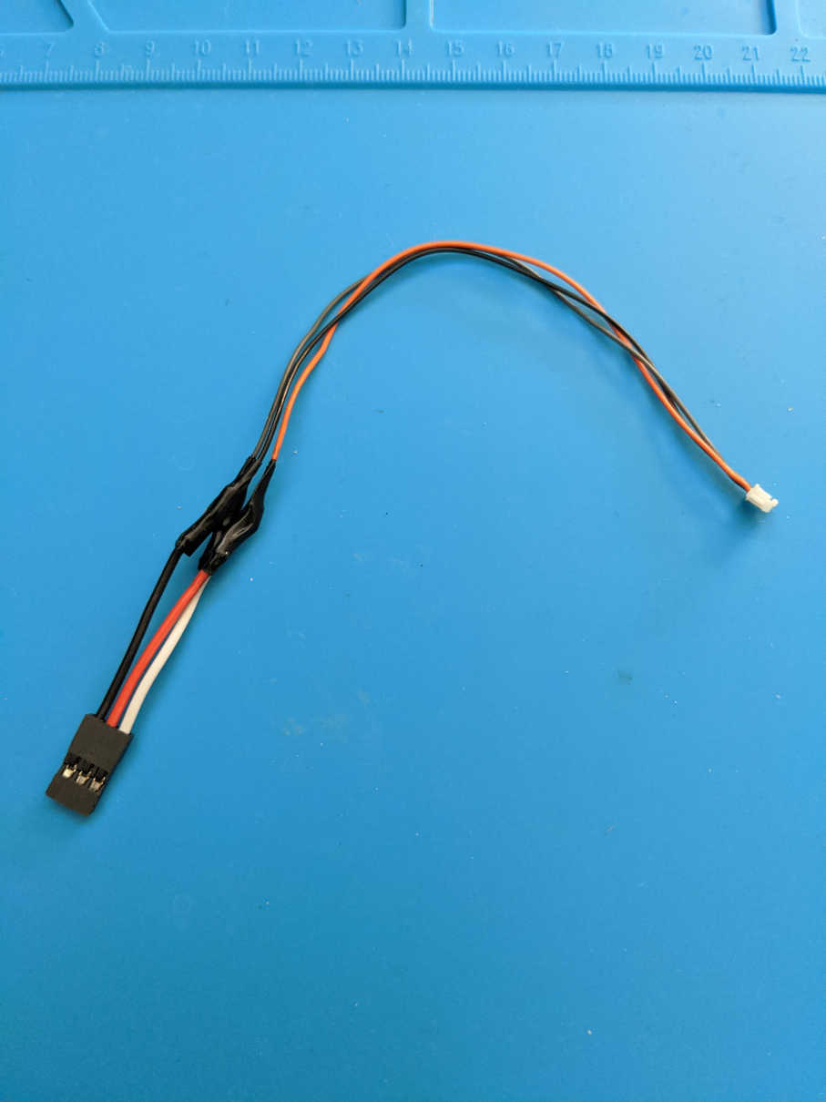
Custom Plug Adapter
In order to make the remote receiver breadboard-compatible, I needed to make my own custom adapter. I bought an additional remote receiver cable and soldered its wires to the wires of a standard servo connector (see image below).
Wiring it Up
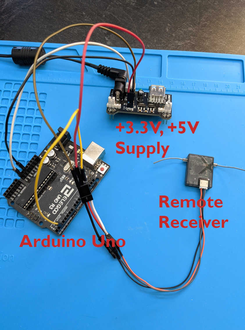
IMPORTANT: THE REMOTE RECEIVER REQUIRES +3.3V ONLY! Do not connect more than +3.3V to the remote receiver’s power line!
I used an Arduino Uno to read the serial data stream from the remote receiver and an external +5V / +3.3V power supply to power the circuit. I suspected that I might run into current draw limitations on the Uno’s 3.3V supply, so I instead used an external 3.3V power supply for the remote receiver. I also powered the Uno with a 5V output from the external supply via the Uno’s Vin pin. I then connected the remote receiver’s serial data wire to Arduino Uno pin 2. I used the Arduino SoftwareSerial library to read the serial stream.
Software
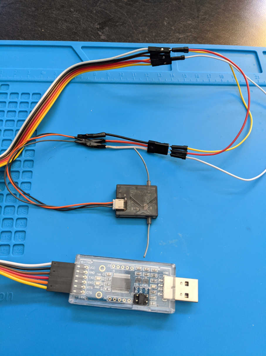
In order to determine which protocol my remote receiver used, I probed its serial output via a serial-to-USB converter and serial port monitoring software. I figured out which protocol was used by comparing the second byte of each serial message to the datasheet. Mine ended up using the 22ms/2048 DSMX protocol.
Getting Serial Data
I used the SoftwareSerial library to ‘convert’ Arduino Uno pin 2 to a serial input. I labelled this serial port as Serial1. The default baud rate for the remote reciever is 115200!
In the Arduino’s loop() function, I had the Uno listen to the remote receiver’s serial connection until it received a serial byte. When a byte was received, the byte was then passed on to my processing function.
SoftwareSerial Serial1(2, 3);  // (rx, tx) receiver's serial port

void setup() {
    while (!Serial);  // Wait for serial console to open
    Serial.begin(115200);  // Arduino's port
    Serial1.begin(115200);  // Spektrum's port
}

void loop() {
    if (Serial1.available() > 0) {
        uint8_t incomingByte = Serial1.read();  // Get data!
        processByte(incomingByte);
    }
}
Processing the Data
The incoming bytes from the remote receiver needed to be stored in an array for processing. In order to figure out what array index to put the incoming byte into, I needed to figure out some logic to determine the proper index. As described in the datasheet, there was a 22ms delay between each data frame. Therefore, if the time between the current and previous receive was greater than about 10ms, the current byte was the first in a new transmission. I used a counter variable as an array index. Every time a new serial byte was received, the counter/array index was incremented by one. The array index variable was reset to zero when it reached 15, a full frame (the end of the array). Once a full data frame was received and the data array was full, the frame was passed on to another function to extract the channel/servo data.
void processByte(uint8_t inByte) {
    unsigned long currTime = millis();
    if (currTime - prevUpdateTime > 10) {
        // 22ms delay between data frames has passed, reset index
        byteIndex = 0;
    }

    dataBytes[byteIndex] = inByte;  // Add byte to array
    byteIndex++;

    if (byteIndex == sizeof(dataBytes)) {  // If the index is at 16
        // dataBytes is full, time to parse and extract channel
        // data/servo positions
        processFrame();
        byteIndex = 0;
        frameCount++;
    }

    // currTime and prevUpdateTime will be very close when receiving bytes in
    // quick succession When the frame transmission is done, the time will
    // hold constant. Then, when a new frame comes along, the time difference
    // will be large
    prevUpdateTime = currTime;
}
Extracting Channel Data
Before processing each frame and extracting channel data/servo positions, some error-checking was performed to validate the frame was correct. Then, bit masking and bitwise operations were perfomed to extract each channel’s data.
Recall that the first byte in each frame is the number of frames the remote receiver missed or dropped. This never changed from zero during my testing, so I never used this value for anything. However, the second byte in each frame was very important. The value of this byte describes the protocol used by the remote receiver. My receiver’s was 0xA2, which corresponded to the 22ms/2048 DSMX protocol. For some reason, the ID byte occasionally switched to 0xA1 or 0xA3 for a single frame. The rest of the frame seemed normal, but just as a safeguard, I ignored every frame whose ID wasn’t 0xA2.
Recall that the third through 16th byte in each frame contains the channel data as big-endian 16-bit unsigned integers. Every pair of bytes were parsed. The first byte byte in each pair was the ‘high’ byte, and second was the ’low’ byte. First, the channel ID (number) was extracted from the high byte via bitwise operations. Next, the pair of big-endian bytes were converted to standard uint16_t type via bitwise operations to compute the corresponding channel’s value. The result was masked with 0x07FF, which is 2047 in hex.
Next, I converted the channel’s value to fall within the standard servo PWM signal pulse width: between 1000us and 2000us, centered at 1500us. The remote receiver’s datasheet gave an equation to do this. Finally, the channel value was stored in an array, with its index corresponding to the the channel’s ID. Sometimes, the channel ID exceeded 6 for some reason, so I therefore ignored those values.
Also, I stored the previous valid readings just in case an error occurred.
void processFrame() {
    // Expects second byte (protocol ID) to be 0xA2.
    // If not, use previous valid data
    if (dataBytes[1] == 0xA2) {
        for (uint8_t i = 2; i < sizeof(dataBytes); i += 2) {
            uint8_t hiByte = dataBytes[i];
            uint8_t loByte = dataBytes[i+1];
            uint16_t servoVal;
            uint8_t chanID = (hiByte >> 3) & 0xf;  // Extract channel ID

            // Make sure channel ID is less than 6 (range from 0 to 6)
            if (chanID <= 6) {
                // Convert two bytes in big-endian to int
                // https://stackoverflow.com/a/2660326
                servoVal = ((hiByte << 8) | loByte) & 0x07FF;

                // Constrain values to a range, just in case an error occurs
                if (servoVal < 300)
                    servoVal = 300;

                if (servoVal > 1730)
                    servoVal = 1730;

                // Use equation in DSMX datasheet to convert [0 2048] values
                // to standard PWM range [~1000ms ~2000ms] with center at 1500ms
                servo[chanID] = (0.583f * servoVal) + 903;
            }
        }
        // memcpy(dest, src, sizeof);
        memcpy(prevDataBytes, dataBytes, sizeof(dataBytes));
        memcpy(prevServo, servo, sizeof(servo));
    }
    else {
        // Bad reading, use previous (valid) data
        memcpy(dataBytes, prevDataBytes, sizeof(prevDataBytes));
        memcpy(servo, prevServo, sizeof(prevServo));
        numBadReadings++;
    }
}
Results
I am very happy with the results of my code. It was able to read the six channels coming from my transmitter without error. The code is relatively light weight, both in terms of memory and computation time. Before I implement this on board my flight computer, I will likely add a few more error checks, just to be extra safe.
Code
Here is the entire Arduino code I wrote. Please cite my blog if you plan on using it in your project!
// ----------------------------------------------------------------------------
// READ RC CHANNEL DATA FROM SPEKTRUM DSMX REMOTE RECEIVER
//
// Code By: Michael Wrona | mwrona.com
// ----------------------------------------------------------------------------
/**
 * Sample Packet:
 *  00 a2 0b fe 2b fe 13 fe 21 32 1b fe 30 00 01 30
 *  ChID: 1     5     2     4     3     6     0
 */


#include <string.h>
#include <SoftwareSerial.h>

void processByte(uint8_t inByte);
void processFrame();

uint8_t byteIndex {0};
uint8_t frameCount {0};  // Number of evaluated frames
uint8_t dataBytes[16];  // Array to store the entire 16 byte packet
uint8_t prevDataBytes[16];  // Store prev. ver. in case of data read error
uint16_t servo[7];  // Array to hold channel data (7 in total)
uint16_t numBadReadings {0};  // Number of missed frames (counter)
uint16_t prevServo[7];  // Store prev. correct readings
unsigned long prevUpdateTime {0};

SoftwareSerial Serial1(2, 3);  // Spektrum serial port


void setup() {
    while (!Serial);  // Wait for serial console to open
    Serial.begin(115200);  // Arduino's port
    Serial1.begin(115200);  // Spektrum's port
}


void loop() {
    if (Serial1.available() > 0) {
        uint8_t incomingByte = Serial1.read();  // Get data!
        processByte(incomingByte);
    }
}


void processByte(uint8_t inByte) {
    unsigned long currTime {millis()};
    if (currTime - prevUpdateTime > 10) {
        // 22ms delay between data frames has passed, reset index
        byteIndex = 0;
    }

    dataBytes[byteIndex] = inByte;  // Add byte to array
    byteIndex++;

    if (byteIndex == sizeof(dataBytes)) {  // If the index is at 16
        // dataBytes is full, time to parse and extract channel
        // data/servo positions
        processFrame();
        byteIndex = 0;
        frameCount++;
    }

    // currTime and prevUpdateTime will be very close when receiving bytes in
    // quick succession When the frame transmission is done, the time will
    // hold constant. Then, when a new frame comes along, the time difference
    // will be large
    prevUpdateTime = currTime;
}


void processFrame() {
    // Expects second byte (protocol ID) to be 0xA2.
    // If not, use previous valid data
    if (dataBytes[1] == 0xA2) {
        for (uint8_t ii = 2; ii < sizeof(dataBytes); ii += 2) {
            uint8_t hiByte {dataBytes[ii]};
            uint8_t loByte {dataBytes[ii+1]};
            uint16_t servoVal{};
            uint8_t chanID {(hiByte >> 3) & 0xf};  // Extract channel ID

            // Make sure channel ID is less than 6 (range from 0 to 6)
            if (chanID <= 6) {
                // Convert two bytes in big-endian to int
                // https://stackoverflow.com/a/2660326
                servoVal = ((hiByte << 8) | loByte) & 0x07FF;

                // Constrain values to a range, just in case an error occurs
                if (servoVal < 300)
                    servoVal = 300;

                if (servoVal > 1730)
                    servoVal = 1730;

                // Use equation in DSMX datasheet to convert [0 2048] values
                // to standard PWM range [~1000ms ~2000ms] with center at 1500ms
                servo[chanID] = (0.583f * servoVal) + 903;
            }
        }
        // memcpy(dest, src, sizeof);
        memcpy(prevDataBytes, dataBytes, sizeof(dataBytes));
        memcpy(prevServo, servo, sizeof(servo));
    }
    else {
        // Bad reading, use previous (valid) data
        memcpy(dataBytes, prevDataBytes, sizeof(prevDataBytes));
        memcpy(servo, prevServo, sizeof(prevServo));
        numBadReadings++;
    }
}